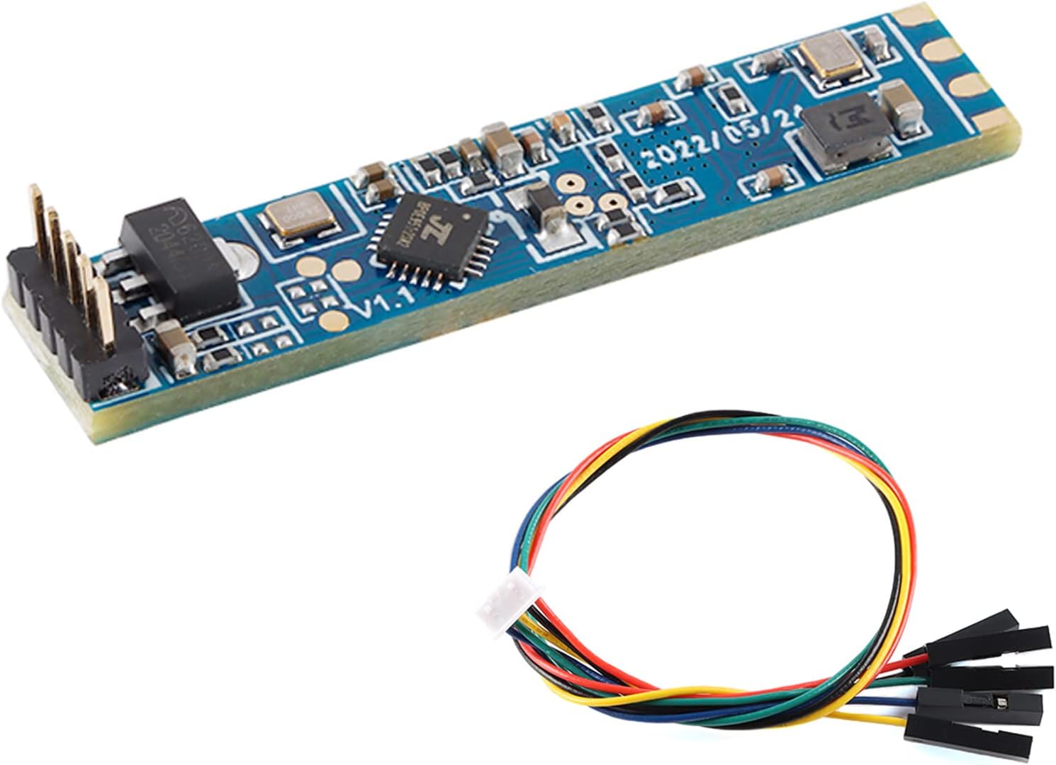
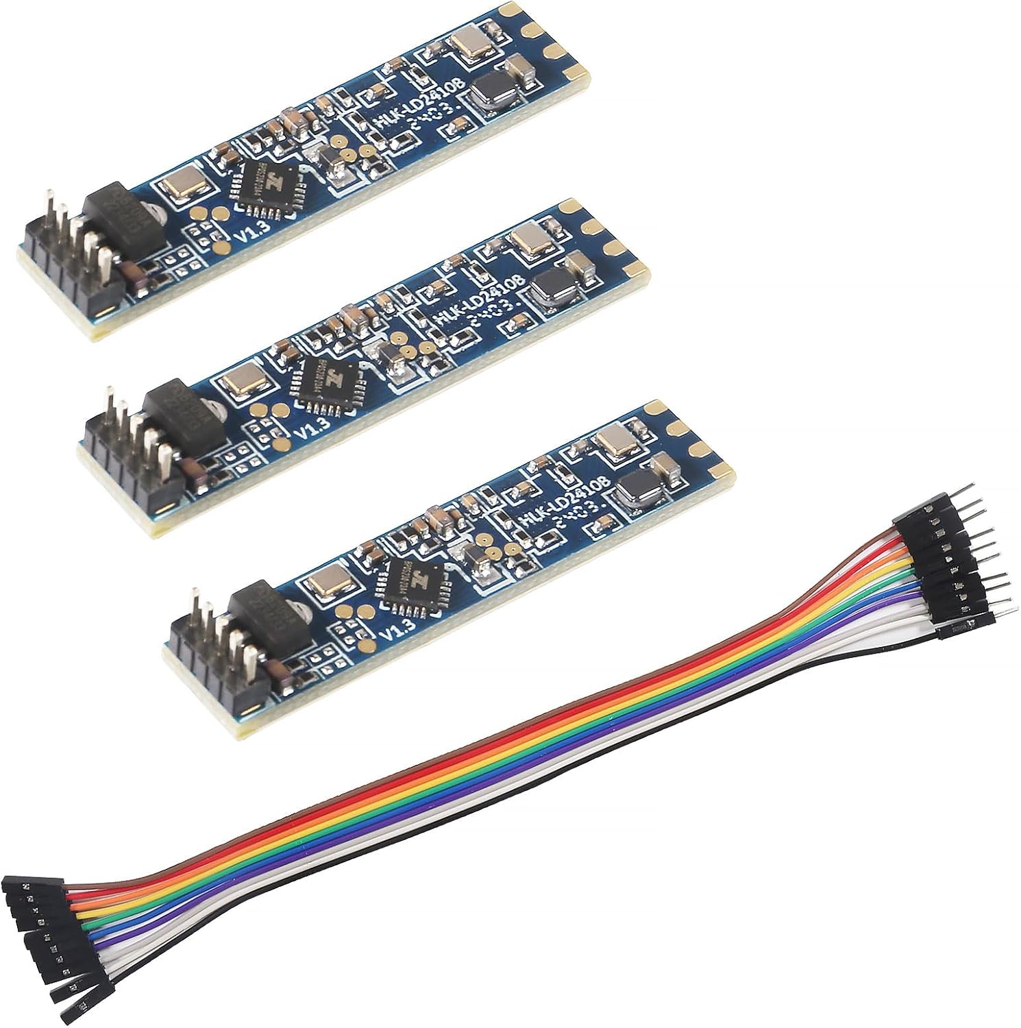
- LD2410C · 3-pack
- Bluetooth: tune it from your phone
- Cable included
Four wires carry an LD2410: 5V, ground and a crossed serial pair. Which pins, which UART and which library depend on the board in your hand.
Revised September 2026Power the sensor from the board's 5V pin, share ground, and cross the serial lines: sensor TX to the board's RX, sensor RX to its TX. Use a hardware UART at 256000 baud. On a classic ESP32 that means GPIO16 (RX2) and GPIO17 (TX2).
A classic ESP32 dev board has three hardware UARTs, and UART2 on GPIO16 and GPIO17 is free on most of them. That makes it the least fussy home for an LD2410.
The sensor's TX and OUT pins swing to 3.3V, which the ESP32 reads directly, and the ESP32's 3.3V TX is what the sensor's RX expects. No level shifter needed. On an LD2410C the pin order from pin 1 is TX, RX, OUT, GND, VCC; the original and B boards start with OUT instead, so read the pinout for your version.
Keep the jumpers short, especially the 5V pair. A USB port that sags under an ESP32's Wi-Fi bursts plus the radar shows up as brownout resets. A decent 1A USB supply fixes it.
For firmware, ESPHome's built-in component is the quickest route to Home Assistant. The ESPHome YAML walkthrough uses exactly these pins, so the config drops in unchanged.
| Board | Sensor TX goes to | Sensor RX goes to | Sensor VCC from | Notes |
|---|---|---|---|---|
| ESP32 dev board | GPIO16 (RX2) | GPIO17 (TX2) | 5V / VIN | UART2, logger stays on UART0 |
| ESP32-C3 dev board | GPIO20 | GPIO21 | 5V | Logger on USB, so the UART pins are free |
| Seeed XIAO ESP32-C3 | D7 (GPIO20) | D6 (GPIO21) | 5V pad | Same chip, XIAO labels |
| Wemos D1 Mini / ESP8266 | RX (GPIO3) | TX (GPIO1) | 5V | Disable the logger; unplug TX to flash over USB |
| ESP8266, swapped UART | GPIO13 (D7) | GPIO15 (D8) | 5V | Keeps USB logging usable |
| Arduino Mega | RX1 (pin 19) | TX1 (pin 18) via divider | 5V | Serial1, 5V logic |
| Arduino Uno | SoftwareSerial pin | SoftwareSerial pin via divider | 5V | Lower the sensor's baud first |
Pin names from each board's standard pinout. Sensor pin order differs between LD2410 versions; check your module's pinout before wiring.
The ESP32-C3 has two hardware UARTs and a built-in USB serial port for logs. With the logger on USB, the regular UART pins are yours.
GPIO20 (RX) and GPIO21 (TX) are the usual choice. On a Seeed XIAO ESP32-C3 they are labelled D7 and D6, and the board's 5V pad carries USB power for the sensor. The C3 can route a UART to other free GPIOs too, but steer clear of its strapping pins, GPIO2, GPIO8 and GPIO9.
uart:
id: ld2410_uart
rx_pin: GPIO20
tx_pin: GPIO21
baud_rate: 256000
parity: NONE
stop_bits: 1Seeed also makes a 24GHz mmWave board sized for its XIAO line, built on an LD2410-family radar. If you would rather not assemble anything, the AKAMATIS v2.2 is a finished version of the same idea: an LD2410B wired to a Seeed ESP32-C3 with an external Wi-Fi antenna, in a case, running ESPHome.
A XIAO plus an LD2410C fits in a very small printed box. The enclosure guide covers the clearance the radar needs in front of it.
One C3 caveat: if you enable the logger on a hardware UART instead of USB, it can collide with the pins you picked for the sensor. Leave logging on USB and the conflict never appears.
LD2410C single module |
LD2410C 3-pack with cables |
LD2410B-P module |
LD2410 original module |
LD2410B Test Kit | |
| Type | Module | Module | Module | Module | Test kit |
| Version | LD2410C | LD2410C | LD2410B-P | LD2410 | LD2410B |
| Pack | 1 module | 3-pack | 1 module | 1 module | 1 module |
| Bluetooth | Yes | Yes | Yes | — | Yes |
| Cable | — | Yes | — | Yes | — |
| Get the module | Get the module | Get the module | Get the module | Get the module |
A D1 Mini's ESP8266 has one full-duplex hardware UART, and by default it carries both USB flashing and log output. To read an LD2410 at 256000 baud, you hand that port to the sensor.
In ESPHome, set the logger's baud_rate to 0 so it stops writing to the serial port. Then put the UART on GPIO1 (TX) and GPIO3 (RX), the pins marked TX and RX on a Wemos D1 Mini. Logs still reach you over Wi-Fi.
There is a second option: the ESP8266 can swap UART0 onto GPIO15 (TX) and GPIO13 (RX), marked D8 and D7 on the D1 Mini. That keeps the USB pins clear for flashing. Software serial is the option to skip; bit-banged serial on an ESP8266 is unreliable at 256000 baud.
The ESP8266 has less memory and a single core, so leave engineering mode off in daily use. For a new build, an ESP32-C3 board costs about the same and removes the UART juggling entirely.
The LD2410B test kit puts the Bluetooth module on a carrier board with a cable, ready to plug into a PC or a phone app. Confirm the radar and its settings, then move on to your ESP32.
Get the moduleIf you want your own firmware rather than ESPHome, open-source Arduino libraries parse the LD2410's frames for you. The ncmreynolds ld2410 library is a common starting point on ESP32 and other boards with a spare hardware serial port.
#include <ld2410.h>
ld2410 radar;
void setup() {
Serial.begin(115200);
Serial2.begin(256000, SERIAL_8N1, 16, 17);
radar.begin(Serial2);
}
void loop() {
radar.read();
if (radar.presenceDetected()) {
Serial.println(radar.stationaryTargetDistance());
}
}The pattern is the same in any library: open a hardware serial port at 256000, hand it to the parser, and call its read function often. Libraries differ in naming and in which configuration commands they support, so check the examples that ship with the version you install.
Configuration commands let your sketch set the maximum gates, the timeout and per-gate sensitivity. Setting them in the phone app or PC tool first is often faster.
Print what the library reports to the serial monitor before you write any automation logic. Walk away from the sensor and back again, then sit still for a minute. If the stationary flag drops while you sit, raise the sensitivity of the gate you sit in or move the sensor closer; the numbers you see here are the same energy values the configuration tools show.
An Uno runs 5V logic, and the LD2410's serial pins are 3.3V parts. Its TX output reads fine on the Uno, but the Uno's 5V TX should not go straight into the sensor's RX.
A two-resistor divider is enough: 1kΩ from the Uno's TX pin to the sensor RX, and 2kΩ from the sensor RX to ground. That brings 5V down to about 3.3V. A small bidirectional level-shifter board does the same job and tidies the wiring.
| Arduino | Serial to use | Plan |
|---|---|---|
| Uno, Nano | SoftwareSerial | Lower the sensor's baud first |
| Mega 2560 | Serial1 (pins 18, 19) | 256000 on hardware serial |
| Leonardo, Micro | Serial1 | Hardware port, USB stays free |
That last option is the simplest Arduino LD2410 project of all. Configure range and timeout once over Bluetooth, then treat OUT as a presence switch.
Whichever board you use, tie the grounds together first and connect the data lines second. That order spares the sensor's pins from stray current while you plug things in.
GPIO16 (RX2) and GPIO17 (TX2) on a classic ESP32. Sensor TX goes to GPIO16 and sensor RX to GPIO17.
Yes, on the hardware UART. Turn off serial logging, use GPIO1 and GPIO3 or the swapped GPIO15 and GPIO13, and power it from the 5V pin.
No. Both sides use 3.3V logic. You only need one with a 5V board such as an Arduino Uno, on the line into the sensor's RX.
Not reliably with SoftwareSerial. Lower the module's baud rate first, use a board with a spare hardware port, or read the OUT pin instead.
Seeed sells an LD2410-family mmWave board sized for XIAO. The AKAMATIS v2.2 is a finished sensor built on a Seeed ESP32-C3 with an LD2410B.
Best LD2410