Top modules

LD2410 Pinout, Baud Rate and Power Supply

Five pins, one serial port at 256000 baud and a 5V rail. The pin order changes between boards, so check yours before the iron gets hot.

Revised September 2026
Quick answer

Original LD2410 and LD2410B count from pin 1 as OUT, TX, RX, GND, VCC. The LD2410C runs TX, RX, OUT, GND, VCC. Feed 5V from a supply good for 200mA, plan on roughly 80mA average draw, and open the port at 256000 baud, 8N1, 3.3V logic.

  • LD2410S is the exception: 3.3V supply and 115200 baud
  • Sensor TX goes to your board's RX, and the other way round
  • OUT sits high (3.3V) while someone is present
First breadboard build1 LD2410C single module
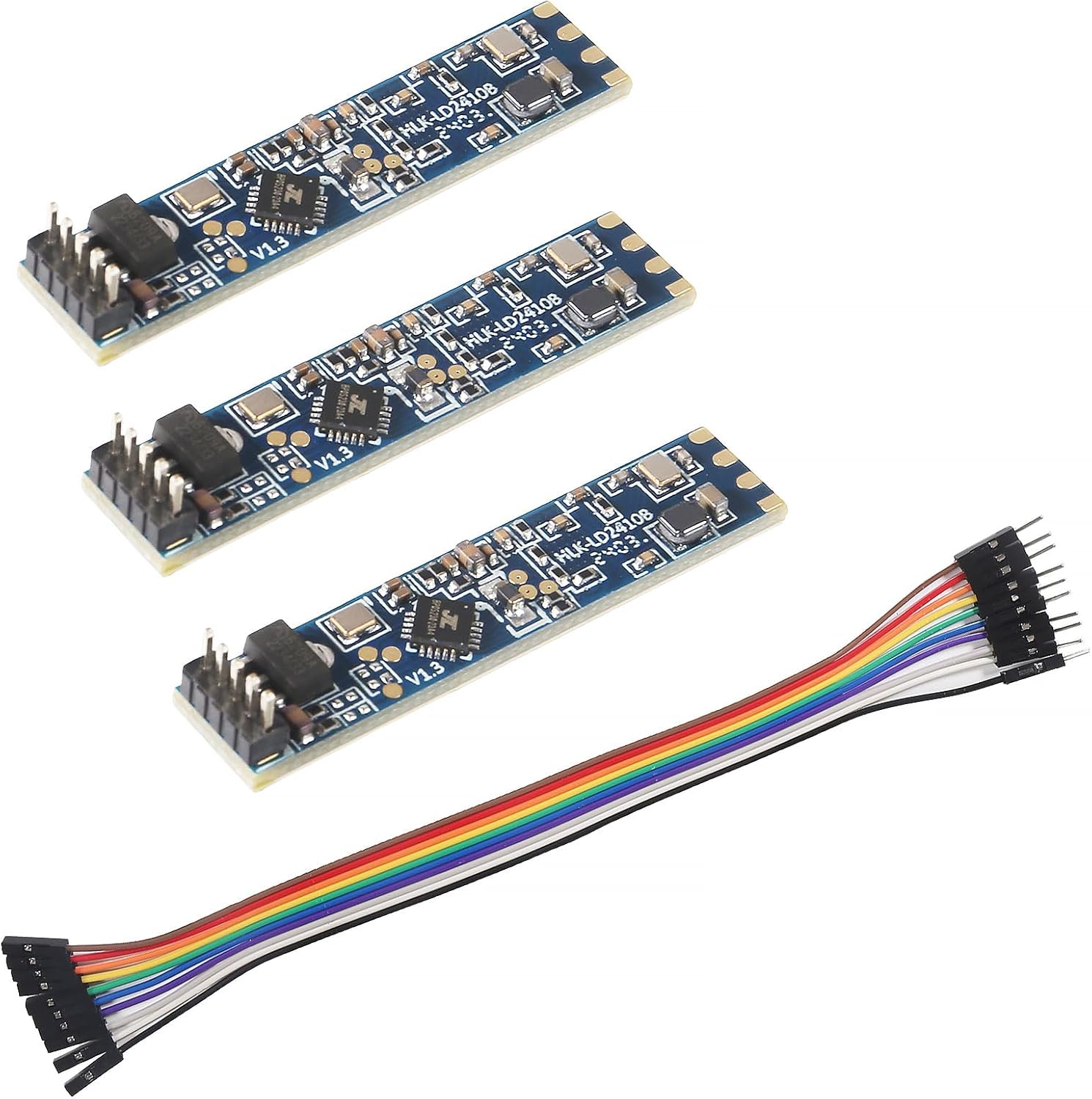
LD2410C single module
Its 2.54mm pitch holes take a standard header and ordinary Dupont jumpers.
  • LD2410C · 1 module
  • Bluetooth: tune it from your phone
  • 24GHz radar: sees people sitting still
Get the module
3.3V battery node2 LD2410S low-power module
LD2410S low-power module
The S version runs from 3.0–3.6V and idles at a tiny fraction of the C's current.
  • LD2410S · 1 module
  • 24GHz radar: sees people sitting still
Get the module
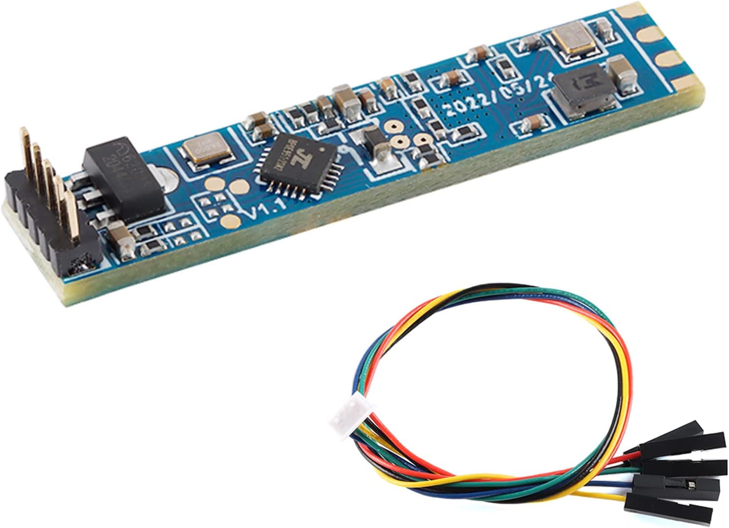
Slim enclosure3 LD2410 original module
LD2410 original module
The 7x35mm original ships with a cable that adapts its fine-pitch pads to 2.54mm jumpers.
  • LD2410 · 1 module
  • Cable included
  • 24GHz radar: sees people sitting still
Get the module

Read pin 1 off your board's silkscreen

Every LD2410 variant has five connections, but they are not in the same order. Wire a C with a diagram drawn for the original and you put 5V on the serial line.

The original LD2410 and the Bluetooth LD2410B share a slim 7x35mm board with five pads at 1.27mm pitch. Hi-Link numbers them OUT, UART TX, UART RX, GND, VCC from pin 1. The LD2410C is a squarer 16x22mm board with holes at the standard 2.54mm pitch, and its order starts with the serial pins: TX, RX, OUT, GND, VCC.

  • Original and B: OUT, TX, RX, GND, VCC. Fine pitch, so use the adapter cable or a 1.27mm header.
  • B-P: the same B board with pins already fitted.
  • C: TX, RX, OUT, GND, VCC. Takes a normal header and breadboard jumpers.
  • S: 3V3, GND, OT1 (serial TX), RX, OT2 (presence output). Different voltage, different baud.

GND and VCC sit side by side at pins 4 and 5 on all three 5V boards. That is the one constant worth memorising. For everything else, trust the print on the board you hold over any diagram drawn for a different version.

Crossing the serial lines is the most common first-day fault: sensor TX goes to your microcontroller's RX pin, sensor RX to its TX.
Reference

Pin 1 to pin 5 on every board

PinLD2410 and LD2410BLD2410CLD2410S
1OUT (presence, 3.3V high)UART TX3V3 power in
2UART TXUART RXGND
3UART RXOUT (presence, 3.3V high)OT1 = UART TX
4GNDGNDRX
5VCC 5VVCC 5VOT2 = presence output
Pitch1.27mm2.54mmsee board
Default baud256000256000115200

Pin numbers from Hi-Link's module manuals. The LD2410B-P is a B with the header already fitted, so it follows the B column.

Open the serial port at 256000 8N1

Out of the box, the 5V boards talk at 256000 baud, 8 data bits, no parity, 1 stop bit. That speed is unusual, and it trips up software serial libraries and cheap USB adapters.

Pick a hardware UART whenever you can. On a classic ESP32 that is UART2 on GPIO16 and GPIO17; on an ESP32-C3 any free GPIO pair routed to a hardware UART works. A CH340 or CP2102 USB adapter handles 256000 on a PC, which is how Hi-Link's configuration tool connects.

  • Data frames start with the bytes F4 F3 F2 F1 and end with F8 F7 F6 F5.
  • Command frames start with FD FC FB FA and end with 04 03 02 01.
  • Normal mode reports target state, moving and still distance, and energy.
  • Engineering mode adds the energy value of every gate.

You can lower the baud rate with a configuration command, from the phone app on Bluetooth boards, or with the ESPHome baud_rate select. Options run from 9600 up to 460800. Drop to 115200 if your board only offers a software serial port, then change your code to match.

The LD2410S breaks the pattern: it defaults to 115200 and uses its own protocol, covered on the version comparison. For the full frame layout, the datasheet walkthrough goes byte by byte.

Board comparison

Pin-friendly boards side by side

LD2410C 3-pack LD2410C 3-pack LD2410B Bluetooth module LD2410B Bluetooth module LD2410B-P module LD2410B-P module LD2410 original module LD2410 original module LD2410S low-power module LD2410S low-power module
TypeModuleModuleModuleModuleModule
VersionLD2410CLD2410BLD2410B-PLD2410LD2410S
Pack3-pack3-pack1 module1 module1 module
BluetoothYesYesYes——
Cable—Yes—Yes—
Get the module Get the module Get the module Get the module Get the module
Datasheet

Every spec of the top boards

LD2410C single module
Model
HLK-LD2410C
Frequency band
24GHz ISM (24.125GHz centre)
Radar type
FMCW (frequency-modulated continuous wave)
Detects
Moving, still, micro-motion, seated and lying people
Maximum sensing distance
5m (some packs quote up to 6m)
Distance resolution
0.75m per gate
Detection angle
±60°
Supply voltage
5V
Logic level
3.3V UART and OUT pin
Interfaces
GPIO (OUT pin) and UART
Default baud rate
256000, 8N1
Header
5 pins at 2.54mm pitch
Module notes →Get the module
LD2410S low-power module
Model
HLK-LD2410S
Frequency band
24GHz ISM
Detects
Moving and stationary people
Range, moving people
0.2–8m
Range, stationary people
0.2–4m
Measurement accuracy
±12.5%
Supply voltage
3.3V nominal
Maximum supply voltage
3.6V
Rated current
0.1mA (low-power operation)
Interfaces
UART and GPIO
Configurable
Detection range and reporting frequency
Protocol
LD2410S-specific; not the LD2410B/C command set
Module notes →Get the module
LD2410 original module
Model
HLK-LD2410
Frequency band
24GHz ISM
Radar type
FMCW
Detects
Moving, still, micro-motion, sitting and lying people
Maximum sensing distance
5m
Distance resolution
0.75m per gate
Coverage
Up to 60°
Board size
7 × 35mm
Supply voltage
5V
Logic level
3.3V UART and OUT pin
Interfaces
UART and GPIO (OUT pin)
Default baud rate
256000, 8N1
Module notes →Get the module

Feed it 5V that can source 200mA

Hi-Link asks for a 5V supply able to deliver more than 200mA. The module averages around 80mA, but the radar front end pulls short peaks, and a weak rail shows up as random resets or flickering presence.

On a dev board, take power from the 5V or VIN pin, which comes straight from USB. The 3.3V regulator pin is the wrong source for the 5V boards. Some Hi-Link documents for the B and C list 5–12V on VCC, yet every version recommends 5V, so treat 5V as the target and anything higher as untested territory.

  • USB phone chargers rated 1A or more are plenty for a sensor plus an ESP32.
  • Keep the power leads short; long thin jumpers add drop and noise.
  • A 10–100µF capacitor across VCC and GND near the module steadies a sagging rail.
  • Share ground between the sensor and the microcontroller, always.

The logic side runs at 3.3V even though the supply is 5V. The TX and OUT pins swing to 3.3V, which an ESP32 or ESP8266 reads directly. The RX pin expects 3.3V too, so a 5V Arduino Uno should talk to it through a divider or a level shifter. Wiring for each board lives in the ESP32 and Arduino guide.

Recommended

Skip the soldering on the first wiring job

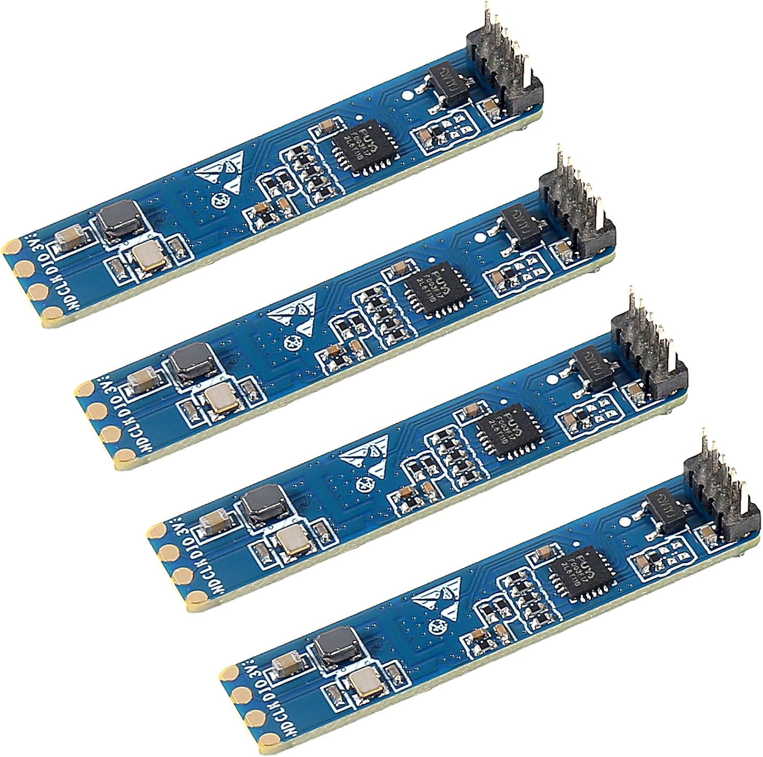
LD2410C 3-pack with cables
Best for jumper-wire wiring LD2410C 3-pack with cables

Three C modules with cables in the box, so VCC, GND, TX and RX reach your dev board without solder. The C's 2.54mm pitch is the easiest LD2410 pinout to live with.

Get the module

Work out the power bill before you pick a battery

Around 80mA at 5V is roughly 0.4W, continuously. Over a day that adds up to about 9.6Wh for the radar alone, before your microcontroller and its Wi-Fi radio join in.

That number decides the build. A 2,000mAh USB power bank feeds a C and an ESP32 for well under a day, so the 5V boards belong on mains or USB power. If the sensor must run from cells, pick the LD2410S, which Hi-Link rates at about 0.1mA average when it reports once a second.

BoardSupplyTypical drawBest power source
LD2410, B, B-P, C5Vabout 80mA averageUSB or mains adapter
LD2410S3.0–3.6Vabout 0.1mA at a 1Hz report rateBatteries
  1. Add your microcontroller's draw: an ESP32 on Wi-Fi averages far more than the sensor.
  2. Decide whether the controller can sleep; the S can wake it through its presence pin.
  3. Size the supply for peaks, not averages.

Turning Bluetooth off on a B or C, through the app or the ESPHome bluetooth switch, closes the radio to anyone nearby with the app. It does not turn a 5V board into a battery part. For long-life nodes, the LD2410S notes cover the trade-offs.

Visualised

Recommended supply voltage by board

Recommended VCC from Hi-Link's manuals. The S accepts 3.0–3.6V; the others want 5V from a supply rated above 200mA.

Drive a relay straight from the OUT pin

You can skip the serial port entirely. The OUT pin goes high at 3.3V while a person is detected and falls low once the no-one timeout expires.

That makes a standalone occupancy switch possible: sensor, 5V supply and a small transistor or logic-level relay module, no code at all. The pin cannot drive a relay coil directly, so put a transistor, MOSFET or a relay board with an opto-isolated input in between.

  • Set the timeout (default 5 seconds in ESPHome) long enough that reading or typing does not drop the light.
  • Flip out_pin_level if your relay board triggers on low.
  • On boards with a light sensor, the light function can gate OUT so it only fires in the dark.

Parameters you set over serial or Bluetooth are stored on the module, so the OUT behaviour survives a power cut. Configure once with the HLKRadarTool app or a USB adapter, then install the sensor with just three wires: VCC, GND and OUT.

Wiring OUT to a GPIO alongside the UART is also handy in ESPHome. It gives Home Assistant a presence signal that keeps working even while the serial side is busy in engineering mode.

OUT reports presence only. Distance, gate energy and still-versus-moving need the serial connection.
Troubleshooting

Common snags

Is the LD2410 3.3V or 5V?

Both, in a way: the supply pin wants 5V, while the TX, RX and OUT pins use 3.3V logic. The LD2410S is different and runs entirely on 3.3V.

What is the HLK-LD2410 default baud rate?

256000 baud, 8 data bits, no parity, 1 stop bit. The LD2410S defaults to 115200.

Can I power the LD2410 from an ESP32's 3.3V pin?

Not the 5V boards. Use the 5V or VIN pin, which carries USB power, and keep the grounds shared.

How much power does the LD2410 use?

About 80mA average at 5V, roughly 0.4W, and Hi-Link asks for a supply that can deliver over 200mA. That rules out small batteries for the 5V versions.

Why does my LD2410C pinout not match a wiring diagram?

Most older diagrams show the original LD2410 or B, which start with OUT at pin 1. The C starts with TX, so redraw the diagram for your board.

Next build step

Continue the build

Parts bin

Other boards for the job

Best LD2410