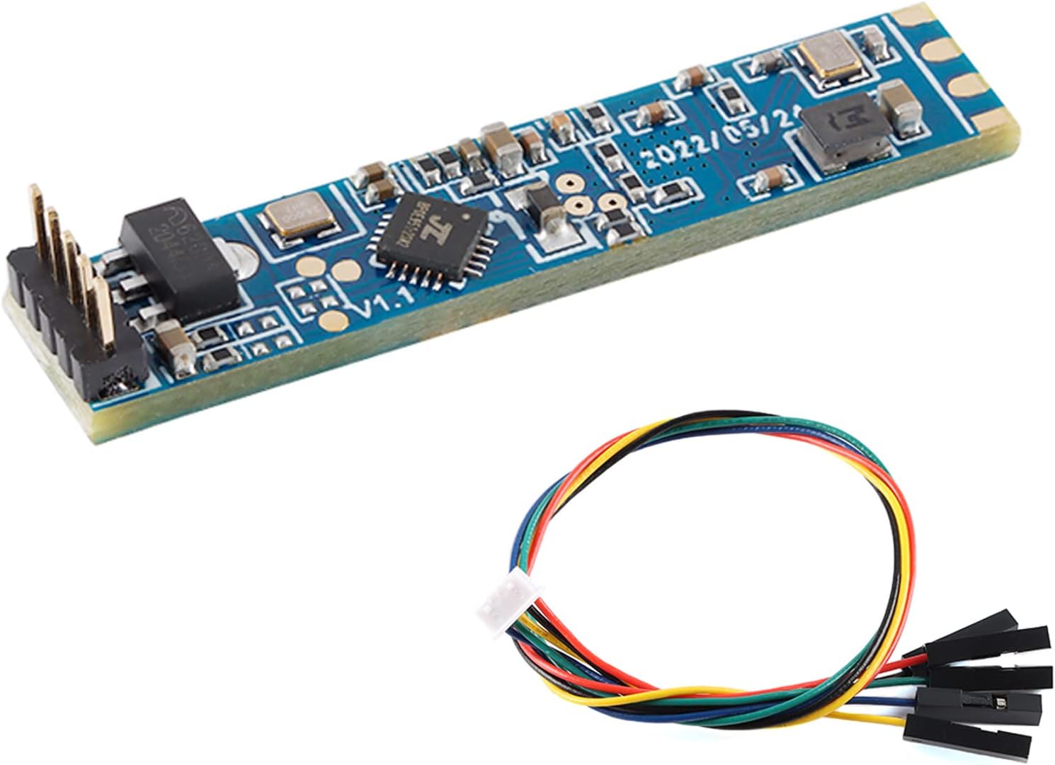
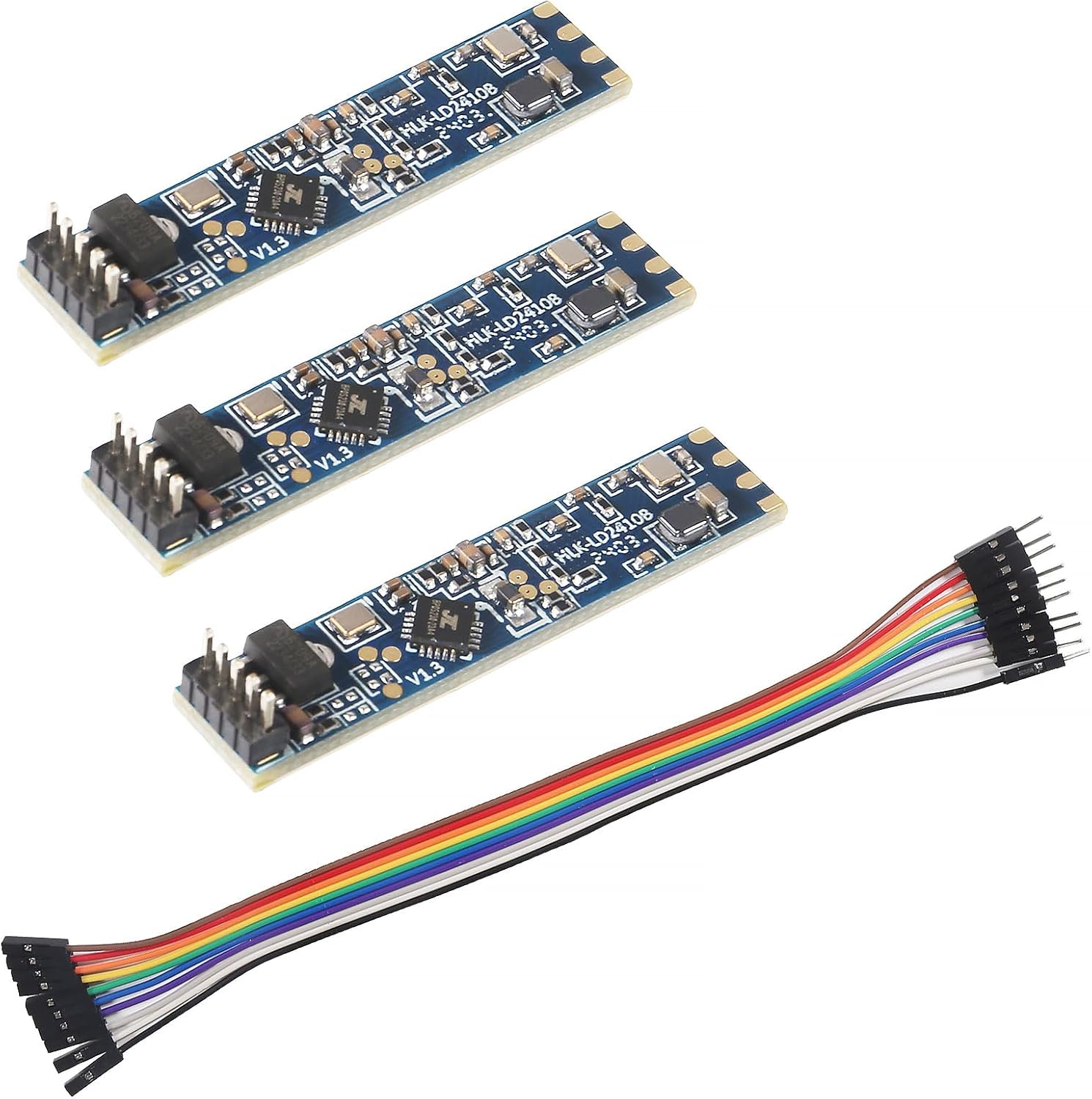
- LD2410C · 3-pack
- Bluetooth: tune it from your phone
- 24GHz radar: sees people sitting still
Hi-Link's LD2410 documents are short, partly translated and spread over two files. The numbers you need for a build are 24GHz, 5V, 3.3V logic, 256000 baud, 0.75m gates and ±60°.
Revised September 2026The LD2410 is a 24–24.25GHz FMCW radar with a 250MHz sweep, rated to 5m (0.75–6m adjustable) with 0.75m distance resolution and a ±60° detection angle. It runs from 5V with a supply able to deliver over 200mA, draws about 80mA on average, and reports over a 3.3V UART at 256000 baud plus one 3.3V GPIO.
Everything else in the datasheet follows from one line: the LD2410 transmits between 24 and 24.25GHz using frequency-modulated continuous wave. That is the license-free 24GHz ISM band, and Hi-Link notes compliance with FCC and CE spectrum rules.
FMCW means the radar sweeps its frequency up in a ramp and compares the echo with what it is sending. The frequency difference reveals the distance to whatever reflected the signal. Repeat the sweeps and tiny changes between them reveal motion, down to the rise and fall of a chest.
The frequency also sets what the radar can see through. Thin plastic, wood, glass and drywall pass 24GHz with some loss; metal reflects it completely. That is useful when you hide the sensor behind a plastic cover, and a nuisance when it spots someone on the other side of a stud wall.
For how that radio pattern turns into coverage in a room, see the range and field-of-view guide.
| Parameter | Datasheet value | What it means for your build |
|---|---|---|
| Working frequency | 24–24.25GHz | ISM band; passes thin plastic, wood and drywall |
| Modulation | FMCW, 250MHz sweep | Measures range, which is why it reports distance |
| Power | DC 5V, supply capability over 200mA | Use a USB or 5V rail, not a 3.3V pin |
| Average current | 80mA | About 0.4W; mains or USB, not coin cells |
| Interfaces | 1 UART, 1 GPIO, 3.3V levels | Direct to ESP32 or ESP8266 pins |
| Detection distance | 0.75–6m, adjustable (5m headline) | Plan on 5m for walking, less for still people |
| Distance resolution | 0.75m | Nine gates, 0 to 8 |
| Detection angle | ±60° | A 120° cone ahead of the antenna side |
| Ambient temperature | -40 to 85°C | Fine for attics, garages and outdoor boxes out of rain |
| Dimensions | 7mm x 35mm (original, B); 16mm x 22mm (C) | Pick the board by the space you have |
Values from Hi-Link's HLK-LD2410 manual V1.03 and the LD2410C manual. The 5V boards share these electrical figures.
The performance table in Hi-Link's manual fits on half a page. Four lines of it decide how you power and connect the module, and they are easy to misread in the translated text.
The LD2410C manual lists 5–12V on the VCC pin with 5V advised. The original LD2410 manual lists 5V only. Treat 5V as the design value for every 5V board and you cannot go wrong.
Pin order changes between those boards. The pinout reference sets them side by side, with the LD2410S and its 3.3V supply for comparison.
LD2410C 3-pack |
LD2410B Bluetooth module |
LD2410 original module |
LD2410S low-power module |
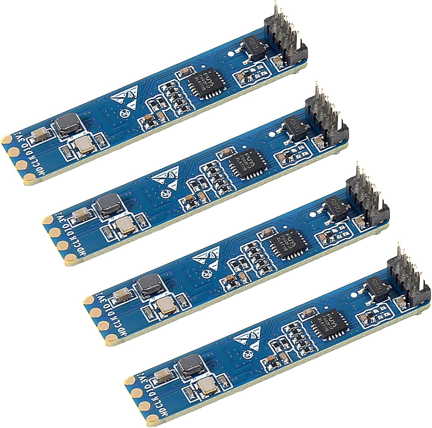
LD2410D module | |
| Type | Module | Module | Module | Module | Module |
| Version | LD2410C | LD2410B | LD2410 | LD2410S | LD2410D |
| Pack | 3-pack | 3-pack | 1 module | 1 module | 4-pack |
| Bluetooth | Yes | Yes | — | — | — |
| Cable | — | Yes | Yes | — | — |
| Get the module | Get the module | Get the module | Get the module | Get the module |
Hi-Link's second document, the serial communication protocol, defines two kinds of frame. Commands you send start with FD FC FB FA and end with 04 03 02 01; data the radar reports starts with F4 F3 F2 F1 and ends with F8 F7 F6 F5.
A normal-mode data frame carries, in order: a data type byte (0x02, or 0x01 in engineering mode), a head byte 0xAA, the target state, the moving target's distance in cm and its energy, the still target's distance and energy, the detection distance, then a tail 0x55 and a check byte 0x00.
| Target state | Meaning |
|---|---|
| 0x00 | No target |
| 0x01 | Moving target |
| 0x02 | Still target |
| 0x03 | Moving and still targets |
Engineering mode is off by default and, per the protocol, is lost at power-off, while gate and timeout settings persist. You rarely need to build frames by hand: ESPHome and the Arduino libraries do it. The ESPHome walkthrough maps these commands to entities.
The LD2410B test kit connects to Hi-Link's PC tool with its own cable, so you can read the firmware version, watch gate energy and see the 0.75m gates in action before you design around them.
Get the moduleThe protocol document lists every factory value. Knowing them tells you what a fresh module does out of the bag and what a factory reset puts back.
One detail hides in that table: per the protocol document, still sensitivity for gates 0 and 1 cannot be set. You cannot tune still detection for the first two gates, roughly the nearest 1.5m, which matters if the sensor sits right beside a bed or desk. Mount it so the person you want to hold sits at gate 2 or beyond.
Sensitivity values run 0 to 100, and a target registers when its energy exceeds the threshold. So a lower number is more sensitive, and 100 switches a gate off. Hi-Link's own example sets gates 3 and 4 to 20 and the rest to 100, confining detection to roughly 2.25–3.75m.
Baud options run 9600, 19200, 38400, 57600, 115200, 230400, 256000 and 460800, and a new rate takes effect after a restart.
Each module in the family has its own document set, in resource folders on Hi-Link's website. For the LD2410 family, look for two files per board: the product manual and the serial communication protocol.
The product manual, sometimes titled user manual or datasheet, covers features, dimensions, pin table, electrical parameters, mounting and radome design. The version widely circulated for the original board is V1.03 from June 2022. The protocol file covers frames, commands and defaults.
Searches for an HLK-LD2410 V1.3 usually mean that manual revision, or a board revision printed on the silkscreen. Revisions update wording and data; the pin table and the 5V, 256000-baud basics stay the same across the 5V boards. The version comparison covers how B, C and S differ.
The manual's radome section is worth reading before you design a case. It recommends keeping the cover about one or one and a half wavelengths from the antenna, 12.4 or 18.6mm at 24.125GHz, with no metal in the path.
24–24.25GHz in the ISM band, with FMCW modulation and a 250MHz sweep bandwidth.
On Hi-Link's website, in the resource folder for each radar model. Each board has a product manual and a serial protocol document.
0.75m per gate in the datasheet. Newer firmware adds a 0.2m option that shortens total range.
Maximum gates 8 for moving and still, a 5-second no-one duration and 256000 baud, with per-gate sensitivities from 50 near the sensor to 15 or 20 far out.
The electrical and radio figures match; the C has its own manual for its 16x22mm board, 2.54mm pitch and different pin order.
Best LD2410